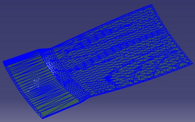
Surface Tessellation
When entering Composites Link from a CATPart, it is
assumed that no mesh exists.
When you click OK in
Export Plies:
- The underlying
surfaces in the entire stacking or the selected plies groups are identified
and cut in turn with all the associated ply boundaries. - This forms regions of constant stacking
between the ply boundaries.
- Each region is tessellated using the Sag
Value and the Step Value.
A core sample is performed on each region.
This determines the extent of each ply.
-
For use in manufacturing, such as laser projection or stress recovery, export target points and references in the layup file.
Thus, you can decide to export surface offsets in the export file. The point of the offset definiton uses the origin of the rosette. -
Run a draping simulation on the plies to regenerate the fiber angles for each ply.
Mapping onto Analysis Mesh
The data in the layup file base on the tessellated triangles can be
mapped onto an analysis mesh, using any analysis tool based on Simulayt
layup technology.
Composites Modeler for Abaqus/CAE
-
In the CM tab, right-click a part containing a shell mesh and create a new layup model based on this analysis mesh.
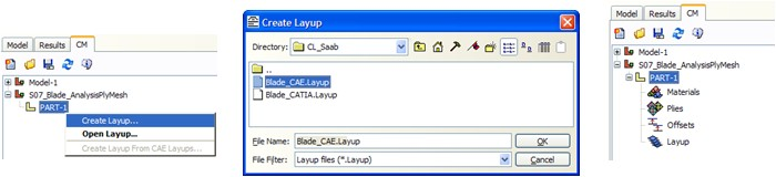
-
Right-click the layup node and choose the Map Layup method to map the plies onto the analysis mesh.
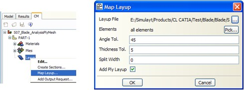
-
Open the material spreadsheet and ensure that the CM Material is correcty linked with the mechanical properties.
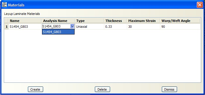
You can now use the layup as if it had been defined in Composites Modeler.
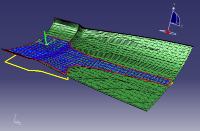
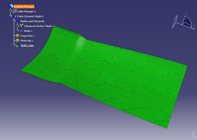
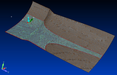
Shell Mesh
Export Mapped Layup File (CATIA Mesh)
When inside a CATAnalysis (in a part or a product environment), you can
create impressive meshes that respect ply boundaries, as show below.
-
To export a layup file base on this mesh, follow the link to the part or to the product with
Composites parts containing the stacking used to create the mesh.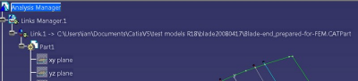
The Composites Link toolbar appears. -
From the Mesh list, select CATIA Mesh.
-
The layup mesh is based on the CATIA analysis mesh: Input a Core Sample Range in the current CATIA units.
-
From the Export File list, select Layup.
-
Click OK.
Composites Link - Retrieves the normal of each analysis element normal from its centroid.
- Performs a core sampling using this normal and the Core
Sample Range.
(This can be time-consuming)
This determines the extent of the ply. - The ply is regenerated using theoretical or actual angles (same as for tessellation).
Note there is no guaranty the finite elements follow the ply boundaries, features such as split may be lost, producibility may be altered or fail.
The resulting layup file contains a full set of information based on the
ply layup, as shown below.
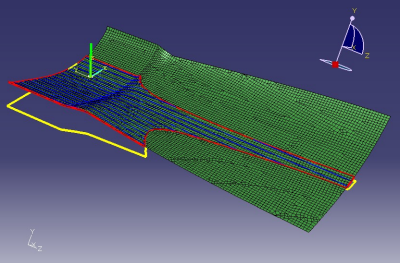
In
this particular case, the elements respect the ply boundaries, the ply
definition is exact.
However, in general, ply boundaries are not
respected, the element-based ply boundaries may be jagged.
Export Mapped Layup File (External Mesh File)
-
Select a type from the Export File list.
A layup file can be exported based on an alternative mesh:
- Abaqus: Abaqus input file (.inp)
- ANSYS: Ansys CBD file (.cbd)
- ANSYS XML
- Nastran: Nastran Bulk Data file (.bdf, .dat, .nas)
- SimXpert
- Composites HDFS
The layup mesh is based on the imported mesh.
The display of the imported mesh is superimposed on the geometry.
Example of .bdf file
Example of a tessellated layup file.
-
Input a Core Sample Range in the current CATIA units.
-
Click OK.
Composites Link - Retrieves the normal of each analysis element normal from its centroid.
- Performs a core sampling using this normal and the input
Core
Sample Range to determine how far from the centroid to look.
Any ply surface beyond this distance is ignored.
Use a number large enough to accomodate differences between the CAD model and the mesh surfaces,
But small enough to avoid detecting several surfaces for a given centroid.
(This can be time-consuming)
This determines the extent of the ply. - The ply is regenerated using theoretical or actual angles (same as for tessellation).
Note there is no guaranty the finite elements follow the ply boundaries, features like split may be lost, producibility may be altered or fail.
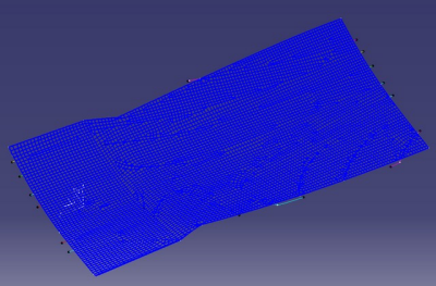
The resulting layup file contains a full set of information based on the ply layup, as shown below.
In this particular case, the elements respect the ply boundaries, the ply definition is exact.
However, in general, ply boundaries are not respected, the element-based ply boundaries may be jagged. If required, select the Export Cores check box to include a solid core within a laminate stack.
-
You can consider the true thickness of the core at the element centroid
(and included in the BDF ofr CDB file if the Ignore Thickness option is cleared in the Export Options).
Import Layup File
You can easily import the layup file based on an analysis mesh into any
analysis application based on Simulayt layup technology and used directly.
This creates a mesh in the program based on the mesh in the layup file.
Composites Modeler for Abaqus/CAE
-
In a model, navigate the CM tab.
-
Right-click the model
where you want to import the layup file, and select Import.Composites Modeler - Opens the layup file.
- Creates a part under the relevant model.
- Places the mesh from the layup file into the new part as an orphan mesh.
- Materials and coordinate systems from the layup file are placed in the model and in the part respectively.
![]()