-
Select the elements to export:
If necessary, select materials to exclude:
All the plies referencing the selected materials are excluded from the export.
This is useful to avoid exporting non-structural plies, such as peel plies, which are of no interest for an analysis.-
If necessary, select the Rename check box to activate the renaming of materials.
This is useful when designers and analysts do not use the same material names
(mainly because of name length restrictions for materials used in the analysis).- Create and store the rename file (spreadsheet stored in CSV
- comma-separated variable) format.
The CATIA name is in column A, while the matching exported name is in column B.
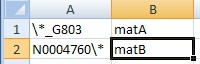
Use \* as a wildcard for CATIA materials, in any position of the name string. - Click ... to select the storage
path of the rename file.
Note that the name of the file appears only if it is valid. - Alternatively, use the variable SLTCompositesLinkMaterialRenameFile to set a default storage path.
- Clear the check box to de-activate the renaming, even is a rename file is selected.
- Create and store the rename file (spreadsheet stored in CSV
- comma-separated variable) format.
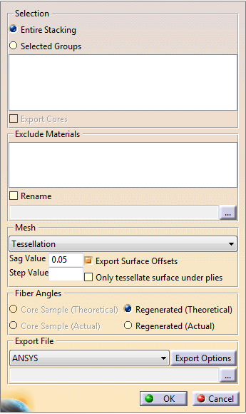
Under Mesh, select how to create the elements on which the ply data are exported.
These elements can be created by: - Tessellation
The underlying surfaces of the plies cut up using every ply boundary and curves referenced by the producibility parameters,
and tessellated to create triangular shell elements on which the ply layup is defined.
This representation reflects the CATIA representation accurately, but is not suitable for the purposes of Finite Element Analysis (FEA).
In this case, the layup file generated by Composites Link need to be mapped onto a layup model based on an analysis mesh in the analysis environment.
This can be done with all analysis products using Simulayt Layup Technology,
such as Composites Modeler for Abaqus/CAE, Composites Modeler for Femap, MSC.Patran Laminate Modeler or Laminate Tools.
The tessellation is controlled by the Sag Value, or the maximum distance between the tessellation and geometry,
and optionally, the Step Value which controls the maximum size of the tessellation triangles.
This option is not available in a product environment. You need to select one of the following options. - CATIA Mesh
This option is available only is a shell mesh for analysis purpose exists in the CATIA model, in a CATAnalysis.
You can select it when the linked model is activated from within the analysis model
(Go in the Analysis workbench and double-click the part containing the stacking).
It is similar to importing a mesh from an external file, except that you select a CATAnalysis instead of a file.
A mesh created in CATIA has the advantage of respecting the ply boundaries. - External Mesh File
A shell mesh is read from a selected Nastran bulk data file (.bdf or .dat), an Ansys CDB, an Abaqus .inp file (the first part only)
or layup file and highlighted in the viewport to make sure it corresponds to the geometry.
Composites Link first maps the ply layup onto this mesh using CATIA core sampling capability
before exporting a layup (or Nastran/Ansys) file containing the ply layup.
This layup file can be imported directly into analysis environments and used without further mapping. - CATIA Mesh Selection
- Tessellation
When exporting plies from a CATIA part to a layup file, the export file can include points used for stress recovery or as reference points for downstream use.
Make sure these points are visible, and gathered under a geometrical set named Target Points under the root level.
They are exported to the point store at the root level of the layup object.-
Data can be offset using a rosette as a reference.
In that case, select the Export Surface Offsets check box.
The point of the offset definition is the origin of the rosette, and the rosette must lie on the surface. -
If required, select the Only tessellate surface under plies check box.
-
Define how the Fiber Angles of exported plies are computed.
Select the Export File format from the list.
The format proposed by default is Simulayt Layup file format.
A shell mesh is defined, on which a ply layup is defined.
The file can be used by tools using or supporting Simulayt layup technology.
Other possible formats are described in the following tasks.-
Click ... to enter the storage path of the export file.
![]()