However, only the shell meshes method provides elements suitable for finite element analysis.
The ANSYS format file exports a PREP7 file in Coded DataBase format (.cdb).
This file can be imported into ANSYS Mechanical APDL analysis tool to define additional data such as loads and boundary conditions.
-
Select ANSYS from the Export File list and click Export Options.
The export mesh is defined by triangular and quadrilateral shell elements corresponding to the tessellation triangles
or shell finite elements, either read from a mesh file or created in CATIA. -
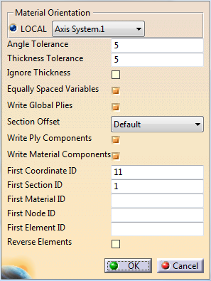
Set the Material Orientation.
From the LOCAL list, select one of the coordinates system found in the stacking.
They are listed by order of first occurrence.
Only rectangular coordinates systems are supported.
Be aware that using an axis system other than the one used for plies generates a large number of Sections. Sections are merged whenever possible using the Angle Tolerance and the Thickness Tolerance.
-
If required, set a Section Offset.
Possible values are Default (in this case, Mid), Top, Mid or Bottom. If required, select the Write Global Plies check box.
- A zero thickness is created for continuous layers within a
section
where that ply does not exist in CATIA.
This reverts to considering that the same layer id represents the same ply in every section, thus the layer is a gobal ply. - This check box works only if the global plies are defined in the direction of the element normals.
- A zero thickness is created for continuous layers within a
section
where that ply does not exist in CATIA.
-
Select the Write Ply Components check box.
In ANSYS, a component is created from the elements mapped from that particular CATIA ply definition.
Since ANSYS does not use the concept of a global ply, the ply component helps you manipulate the data in ANSYS APDL. -
Select the Material Components check box.
In ANSYS, a component is created with the elements that contain each of the materials used in the ply stacking.
Each created component is named from the name used in CATIA materials file. -
Specify a First CoodinateID.
It corresponds to the first LOCAL coordinates system referenced for the layer orientation.
The default and minimum value is 11. -
Enter the ID of the first section, first material, first node and first element.
These ID values are unique.
Usually, ID values correspond to different parts of a model, or different parts to be exported and assembled in ANSYS. -
CATIA surface normals and element normals do not always correspond.
Select the Reverse Element check box to solve this problem and accurately reflect the CATIA stacking in ANSYS.
Note: Write Global Plies cannot create consistent layers if the stacking in ANSYS is not accurate.
Material properties are written to appropriate material cards such as 2D Orthotropic materials.
Data not
defined within CATIA are written as 0. You need to modify them manually
before use.
In ANSYS, use Input command or Utility>
File> Read Input from menu to import the exported CDB file.
Use
Utility> Plot> Elements to plot the elements (EPLOT) and
display the model.