Nastran and SimXpert Export Options

This format exports plies to specialist analysis tools, both for surface tessellations and shell meshes.
However, only the shell meshes method provides elements suitable for finite element analysis.
Nastran files can be imported into numerous analysis tools to define additional data such as loads and boundary conditions.
  1. Select Nastran from the Export File list and click Export Options.

    The export mesh is defined by triangular and quadrilateral shell elements corresponding to the tessellation triangles
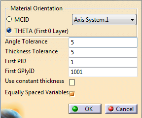
    or shell finite elements, either read from a mesh file or created in CATIA.

  2. Set the Material Orientation
    • MICD uses a coordinates system.
      From the list, select one of the coordinates system found in the stacking.
      They are listed by order of first occurrence.
      Only rectangular coordinates systems are supported. They are written as CORD2R card.
      Be aware that using an axis system other than the one used for plies generates a large amount of properties.  
    • THETA (First 0 Layer) uses an angle with respect to the first edge of each element.
      The orientation of the lowest ply on each element with a nominal direction of 0 degrees is used to define the angle.
      When this element does not exist, the orientation of the lowest ply of an arbitrary direction is used.

  3. PCOMP and PCOMPG cards are created to reflect the stacking with respect to the material orientation.
    Cards are merged whenever possible using the Angle Tolerance and the Thickness Tolerance.
    • The Angle Tolerance is given in degrees, and represents the negative and positive values around the nominal
      (For example, 5 represents a -5/+5 degree tolerance).
    • The Thickness Tolerance is given as a percentage.
    • Select the Use constant thickness check box to ignore the thickening due to shearing, thus reducing the number of properties.
      Be aware it also ignores any taper or thickness change on solid cores.
    • Select Equally Spaced Variables to use only angles and thicknesses that are an integer multiple of the input tolerances.
      For example, with the default Angle Tolerance of 5, the allowed PCOMP layer angles are 0, 10, 20, 30, 40...
      Set the Angle Tolerance to 7.5 for angles of 0, 15, 30, 45...

  4. Define the PID of the first property card (First PID).
    Usually, PID values correspond to different parts of the model.

  5. Specify a first GPlyID corresponding to the first ply in the Stacking.
    These values are exported via the PCOMPG cards.
    Set GPlyID to 0 if you do not want to specify GPlyIDs. PCOMP cards are written instead.

Material properties are written to appropriate Nastran material cards such as MAT8 for 2D Orthotropic materials.
Data not defined within CATIA are written as 0. You need to modify them manually before use.