Once the Detailed Simulation is initialized, do one or several of the following to edit the inputs.
The Forming Simulation is under Forming under the plies group in the stacking.
The geometry is under Geometry. Unhide elements as you need them.
Edit the Blank
-
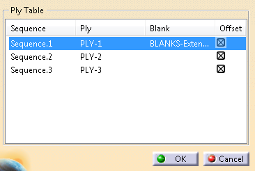
Under Forming simulation.1, double-click Blanks.
The plies are listed in the Ply Table.
-
Pick the cell under Blank in the row of the fist ply.
Select a planar curve to represent the blank.
-
Repeat for all plies.
-
Click OK.
The blank is represented by the dotted line.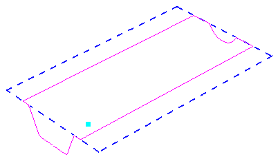
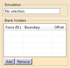
Edit the Blank Holders
-
Click Add Blank Holder
 .
.
-
Select the Forming simulation.
-
Click Add.
A line is added under Blank Holders.
Highlight it. -
Select the boundary representing the blank holder.
-
Enter a Force value.
-
Repeat to add blank holders.
-
Click OK.
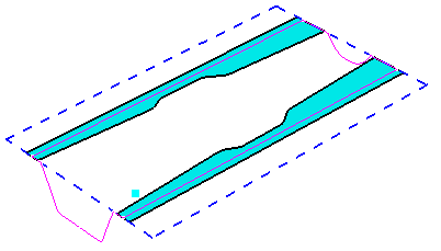
The blank holders are created.
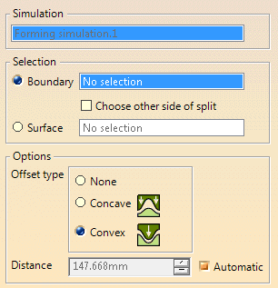
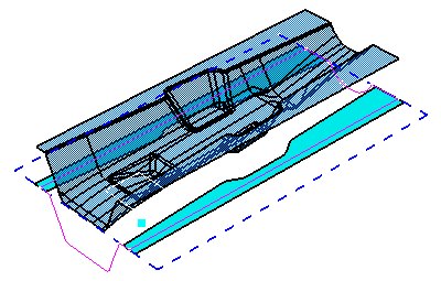
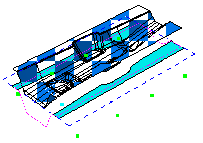
Edit the Punch
-
Click Edit Punch
 .
.
-
Select the simulation you are working on.
-
Decide how the punch is represented (Boundary or Surface) and select the corresponding element.
-
If the punch is defined by a boundary, select the other side of split, if necessary.
-
Either enter the Distance from the forming axis origin, or select Automatic for an automatic comutation.
-
Decide if the punch is Concave or Convex.
-
Validate.
-
Rename the puch for easy identification, and repeat to create all necessary punches.
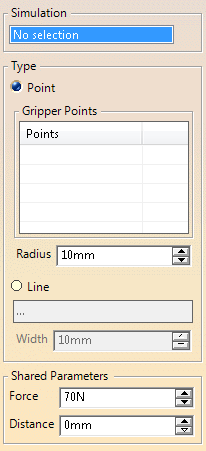
Add Grippers
-
Click Edit Grippers
 .
.
-
Select the Forming simulation.
-
Select the points representing the grippers.
Alternatively, select a Line and enter a Width.
If multiple lines are defines, multiple grippers are created. -
Enter Force, Radius and Distance values.
The grippers are previewed:
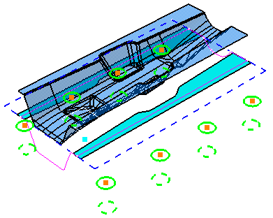
- Plain circles indicate the initial position of the gripper and the corresponding diameter.
- Dashed circles indicate take the distance into account.
-
Click OK.
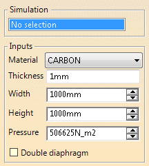
Edit Diaphragm
-
Select Edit Diaphragm.
-
Select the Simulation.
-
Select the material from the list.
-
Enter required information.
-
If necessary, select the Double diaphragm check box for a definition on both sides of the blank stack instead of only on top.
Displacement and pressure can be defined independently on top and bottom diaphragms when editing steps. -
Validate.
-
Update and save the model, you are ready to edit the steps.
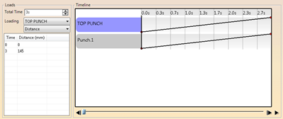
Edit Steps
Steps aim at stabilizing the forming process:
- Stamping the top of the tunnel with the top punch, while mantaining and moving down the blanks with a translation of the grippers.
- Then the side punches (left and right) move all the way down in synchronization with the grippers.
-
Double-click Steps.
-
Set the Total Time.
All times of loads are stored as a fraction of the Total Time. If you change the Total Time, all other times are scaled in proportion. -
Select an element from the Loading list.
-
Right-ckick the last row in the table below, and select Insert Row.
-
Enter Time and Distance.
The Timeline is updated. -
Use the slider below the Timeline to preview loading and movements of the punches, grippers and diaphragms.
You can let the slider run automatically or position it manually. -
Click OK.
The specification tree looks like this:
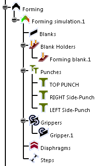
![]()