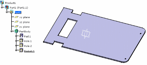
It contains a part with a pad, holes and a pocket.
 |
-
Double-click to activate Part1.
-
Click Create Board
 .
.
You are prompted to select a pad for the board representation. -
Select the pad.
The board turns green. -
Right-click the instance of the board, and select Properties.
Click More... . Select the board or the holes in the specification tree.The objects (board and holes) have automatically acquired technological properties: 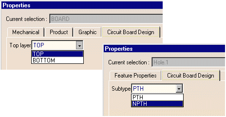
-
Select Export as IDF File
 .
.
The Export dialog box pops up. Select an IDF file.
A board is recognized, all the related features are taken into account and exported to the IDF file. -
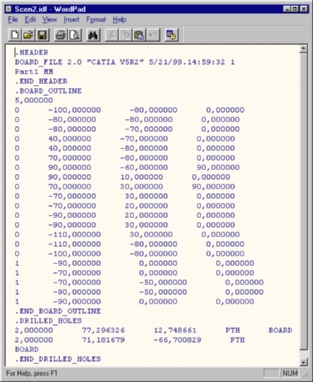
Open the .idf file as a text file. It looks like this: