This section provides information on layers and visualization filters applied to V5 objects:
Layers
Opening Existing Objects
When opening existing objects (whatever the release level on which they have been created), the existing geometry is migrated to the current layer. If you do not want the geometry to be assigned to a layer, you must set the current layer to None before opening existing objects.
Furthermore, if you open existing objects with a current layer set to a layer other than None then close the object without making any changes, you will be prompted to save the object because the geometry was assigned to the current layer when opening the object.
Layer Application
Layers cannot be applied to sub-bodies, they can only be applied to
root bodies. By "root body", we mean a body that is a direct child of the
mechanical part.
Let's have a look at the examples below:
Example 1
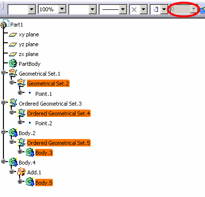
All highlighted elements have no layer property since they are sub-bodies. This behavior applies to geometrical sets, ordered geometrical sets and hybrid bodies (whether these hybrid bodies are aggregated by an ordered geometrical set or by a Boolean operator).
Therefore, when any of these elements is selected, the Layer box is grayed out:
Example 2
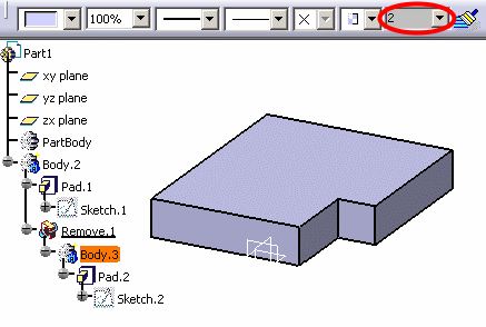
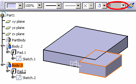
Body.3 is an operated solid body (created before V5R14) and as it is operated, its layer property is ignored and cannot be accessed.
The layer property of Body.3 is rerouted to the layer property of the root body, Body.2 in our example:
Hybrid Bodies and Geometrical Sets
Features of a part body inherit the layer of the part body.
However when the part body is an hybrid body, it can have its own layer different from the layer of the solid feature. In that case, when a layer is assigned to a solid feature inside a part body, the layer does not apply to the part body anymore.
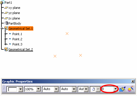
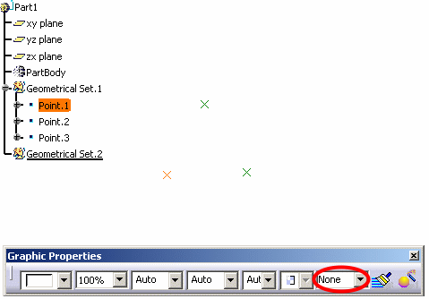
Geometrical sets behave like hybrid bodies, i.e. each sub-element can have its own layer. In the example below, if Geometrical Set.1 is assigned to layer 0:
Link Between Objects and Layers
The link between a given feature or object and a given layer is stored in the representation.
Layer Definition
When pointing to the Layer list, a tooltip indicates
whether the layer definition location is stored in the representation or in the
user settings (i.e. the CATSettings directory).
However, bear in mind that this tooltip is displayed for information
only, you cannot modify the storage location which has been set as
explained below:
- At product level, the definition is stored in the user settings.
- At part body level, the definition (if there is one) is stored in the representation. If no definition is stored in the representation, the part body representation use the definition stored in the user settings.
- For drawings, the definition is stored in the representation.
Visualization Filters
Filter Definition
When pointing to the desired
filter name, a tooltip indicates whether the filter definition
location is stored in the Representation or in the user settings (i.e.
the CATSettings directory).
However, bear in mind that this tooltip is displayed for
information only, you cannot modify the storage location which has
been set as explained below:
- For part objects, the definition (if there is one) is stored in the Representation. If no definition is stored in the Representation, the part objects use the definition stored in the user settings. These visualization filters cannot be administered because it is not relevant for the administrator (he/she would only be able to lock the instance of the currently edited Representation).
- For drawing objects, the definition is stored in the Representation. These visualization filters cannot be administered (same explanation as above).
Visualization Modes
If you apply visualization filters to V4 or V5 objects, note
that these objects have their own way of managing such filters (this
is done through a specific menu named Layer Filter).
Depending on the visualization mode you are using, there are two different
behaviors:
- In Design mode, the .cgr format of the component is changed into the original editable component document (geometry is available). Therefore, the assembly contains the real data and, as explained above, these elements are visualized according to their own filter. This is why some elements might not be filtered as expected.
- In Visualization mode, documents appear in .cgr format. Only the external appearance of the component is visualized (geometry is not available). As .cgr elements are V5 data, there might be discrepancies between the Design mode and the Visualization mode, especially when elements are not visible and when the visualization is loaded from a document that has been previously saved in .cgr format. For instance, when a document has been saved with an active visualization filter hiding some of its elements, these invisible elements are not included in the generated .cgr file.
Regarding dittos, see Layers and Layer Filters for Dittos.