This section provides information about some of the rendering styles you can apply to objects either through the View toolbar, or through the Customize View Mode dialog box:
Wireframe
This rendering style shows edges and lines only. As far as edges are
concerned, when displayed in Wireframe mode, they are applied the
color of the mesh and not the one of the "edges + mesh" mode.
However, the color applied to edges depends on the original edge color:
- Edge color is black (default color).
For each surface or solid, the visualization algorithm retrieves the color of all the object's faces and looks for the dominant color (i.e. the color that is most used). This dominant color will then be used for the display in Wireframe.
For instance, when you display a blue pad with black edges in Wireframe, edges turn blue:Shading with Edges Wireframe 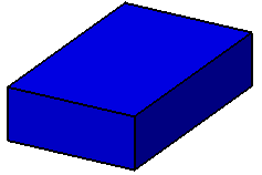
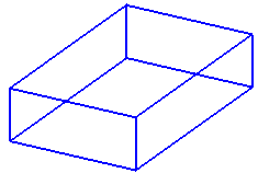
Now if we take a more complex example: a pad with one red face and the rest of the pad in blue. When setting the pad to Wireframe, the pad's edges are displayed in blue which is the dominant color.
- Edge color is other than black.
The color applied to edges is not the dominant color of faces but the color defined in the Color list of the Properties dialog box.
For instance, when you display a blue pad with red edges in Wireframe, edges stay red:Shading with Edges Wireframe 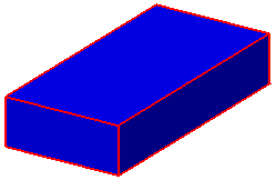
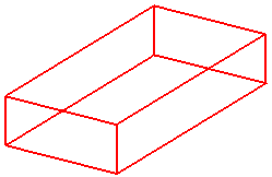
Shading with Edges
This rendering style displays objects in shading mode with all edges, whatever their type (smooth or hidden).
If you modify the object's color, bear in mind that in Shading mode, lineic elements (such as edges or sketches) do not inherit the new color and turn black as shown in the example below:
| Shading with Edges. Red color is not applied to lineic elements |
Edges and Points. Red color is applied to lineic elements |
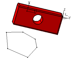 |
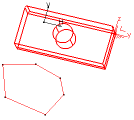 |
For detailed information on color inheritance for Assembly objects, see Displaying and Editing Graphic Properties.
Colored edges from faces
This option available in the View Mode Customization dialog box lets you color edges according to the color applied to the object's faces.
Regarding internal edges, if the two adjacent faces have a different
color each, the edge is colored according to the color of the face whose
bounding sphere's radius is the smallest. The real surface is not taken
into account.
The bounding sphere of a face is a virtual sphere-shaped bounding
volume surrounding the face and whose center and radius are such that
the face is completely within the sphere. Depending on the underlying
feature, there are two possibilities:
- The bounding sphere of the face is the smallest sphere that includes the face (most current case)
- The bounding sphere is larger than the smallest surrounding sphere.
Example 1:
Edges between the green and grey faces of the trapezoid turn
grey when set to Colored edges from faces because
"grey" is the color of the face with the smallest bounding
sphere:
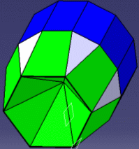 |
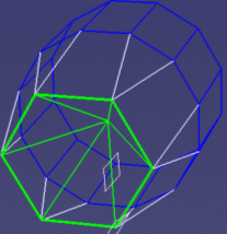 |
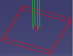
Example 2:
The small square in the center turns red when set to Colored
edges from faces because the bounding sphere of the red face
is smaller than the one of the green face:
 |
 |
To make this visualization mode effective on CATParts earlier than V5R15, you need to upgrade them by running the CATAsmUpgrade batch with the
--force-new-visu
option. For more information about this batch, see Assembly Design User's Guide:
User Tasks: Data Upgrade for Large Assemblies Performance.
Note that .cgr files earlier than V5R15 cannot be upgraded.