![]()
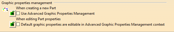
This tab deals with these categories of options:
When Creating Parts
Create an axis system
Select this option if you wish to create a three-axis system which origin point is defined by the intersection of the three default planes that is plane xy, plane yz, and plane zx. When the CATPart document is open, the axis system is displayed both in the geometry and in the specification tree. For more information about Axis System, refer to the Part Design User's Guide.
![]() By default, this option is not selected.
By default, this option is not selected.
Create a geometrical set
Check this option if you wish to create a geometrical set as soon as you create a new part. From V5R15 onward, geometrical sets created with this option on, are located above Part Bodies in the specification tree.
 |
For more information about geometrical sets, refer to Generative Shape Design User's Guide.
![]() By default, this option is not selected.
By default, this option is not selected.
Note: Data contained in the CGR format are saved within the CATPart format when you are saving your part in order to improve performances when working in Assembly Design workbench.
Create an ordered geometrical set
Check this option if you wish to create an ordered geometrical set as soon as you create a new part. For more information about ordered geometrical sets, refer to Generative Shape Design User's Guide.
![]() By default, this option is not selected.
By default, this option is not selected.
Create a 3D work support
Check this option if you wish to create a 3D work on support as soon as you create a new part.
![]() By default, this option is not selected.
By default, this option is not selected.
Display the New Part dialog box
Check this option if you wish to display the New Part dialog box as soon
as you create a new part (using Start >Mechanical Design or File >
New... part).
This dialog box lets you name the new part and access options defining
whether you wish to:
- work in a hybrid design environment
- create a geometrical set
- create an ordered geometrical set
Note that you can also access these options by using Tools>Options as described above. For more information about the New part dialog box, refer to Part Design User's Guide.
Hybrid Design
Enable hybrid design inside part bodies and bodies
Check this option if you wish you to work in a hybrid design environment, that is with bodies that can include wireframe and surface elements.
Note:
If your CATPart document already contains traditional bodies, that is bodies that cannot include surface nor wireframe elements, the application identifies them with a gray icon:
 |
If the option is deactivated, then on insertion of a traditional body (body not allowed to contain wireframe nor surface elements), icons identifying existing bodies likely to include wireframe and surface elements turn yellow.
 |
See hybrid design for reference information. See also the Miscellaneous
list identifying icons available in the Part Design workbench.
![]() By default, this option is selected.
By default, this option is selected.
Enable hybrid design for parameters and relations inside part bodies and bodies
When the option is selected, you can locate parameters and
relations you are creating into the current set (hybrid body or ordered
geometrical set). A dialog box always asks you to confirm the location
you want.
If you do not want to locate the new parameter or relation into the
current set, just click 'No' in the dialog box. It will be created in a
Relations node.
![]() By default, this option is not selected.
By default, this option is not selected.
Locate wireframe and surface elements
-
In a body
-
In a geometrical set
When the option described above is on, meaning that you have chosen to work in a hybrid environment, you still can then choose between inserting wireframe and surface elements within bodies by checking In a body, or within geometrical sets by checking In a geometrical set. For more information about geometrical sets, refer to the Generative Shape Design User's Guide.
![]() By default, the In a body option is selected.
By default, the In a body option is selected.
|
|
Even if Enable hybrid design inside part bodies and bodies is cleared, the Insert in New Body capability ignores the setting. It creates a body which type (hybrid or not) is always the same as the body from which you selected features to place them into the new body. |