![]()
To get to the CCD tab click Tools - Options in the menu bar; Compatibility (under General) in the left pane; and the CCD tab. This tab provides settings for:
Import |
Standard |
|
|
|
The element you import will be placed in a Drawing, the root document of
Drafting. This Drawing uses styles defined in a pre-defined or a customized standard such as ISO, JIS, ANSI, ASME. |
CCD Symbol Catalog |
|
|
|
This is the location of the CCD symbol table model V5 catalogs. Click the Open file button to navigate in the CCD Symbol Catalog Directory Browser to set or change the location for the directory. |
Convert dimensions as |
|
|
|
Select the required option: Dimensions: Geometry: Select this option to keep the graphical aspect. Geometry is exploded into multiple lines, arcs, texts.
|
Convert splines as |
 |
|
Select the required option: Splines: This option will convert CADAM spline to CATIA spline. Polylines: This option assures exact geometric match between CADAM spline and
CATIA spline. You can control the accuracy of the polyline by specifying
the sag value (from 0.01mm to 10mm) in the Sag value box.
|
|
|
Export |
Covert splines as |
 |
|
Select the required option: Splines: This option will convert CATIA spline to CADAM spline. Linear Splines: This option assures exact geometric match between CATIA spline and
CADAM spline. You can control the accuracy of linear splines by
specifying the sag value (from 0.01mm to 10mm) in the Sag value
box.
|
Covert line widths to line weights using CCD Style1 Mappings |
|
|
|
When this option is selected, the CATIA line width is converted to CCD
style 1 line weight using the mapping specified in the CCD Style1
Mappings. The resulting geometry in CCD does not have width. They have
line weight only. If this option clear, then the resulting geometry in CCD will retain the width from CATIA.
|
|
|
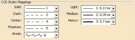
CCD Style1 Mappings |
 |
|
Mapping options apply to imported and exported drawings. These options are
used to control geometry conversion between CATIA and CCD. You can specify the mapping between CCD Style1 geometry, including line weights, and CATIA line types and line widths. The line types and line widths specified are based on the drawing standard set in the Standard option. |
|
|
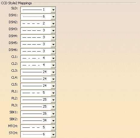
CCD Style2 Mappings |
 |
|
You can specify the mapping between CCD Style2 geometry and V5 line types.
Mappings are based on drawing standard. Note: To see actual line types (not just the numbers), open a new drafting document using the standard specified and then examine these mappings. Not all drafting standards contain line types after line type 20. |
|
|