- Import IGES 2D options:
- Export IGES 2D options:
Impact of Large Scale and Small Scale
You can switch from the Standard Scale to a Large Scale or a Small Scale with Tools > Options > Parameters and Measure >Scale.
- IGES 2D files generated by an export with Large Scale will be correctly handled by V5 with Large Scale.
- When the bounding box of the resulting import is too big for the current scale, a warning message recommends that you define a scale factor in the Import Options or that you adapt the scale configuration.
- IGES 2D files generated by an export with Small Scale will be correctly handled by V5 with Small Scale.
- The import of such files in another configuration (Standard Scale or Large Scale) may result in visualization problems, just like IGES 2D files generated by another application with very small coordinates.
- Other applications like AutoCAD that have a less accurate modeler than V5 are more robust considering the scale of the model and are not impacted.
Import:
Standards
Drafting:
The element you import will be placed in a Drawing, the root
document of Drafting.
This Drawing uses styles defined in a pre-defined or a customized
standard such as ISO, JIS, ANSI, ASME.
For more details about Drafting standards, please refer to
Administration Tasks in the Interactive Drafting User's Guide.
Drafting Standards replace the process of the previous
releases where you had to open,
(eventually modify) and close a new Drawing to recover the standard you
wanted to use
for the data you were going to import. The standard selected in the settings
is taken into account at once.
Unit of the file
By default, the option is set to Automatic and
the unit of import is determined automatically (either millimeter or inch)
for the best possible resulting drawing.
However, in some cases the resulting drawing is not satisfactory and
requires another unit.
Select this unit in the list. Then restart the import.
Destination view
![]()
Select the view in which you want to import the file.
Create end points
![]()
It is not easy to modify and stretch geometry of imported elements the
way you can do it in a V5 native elements.
A solution is to create end points when needed, but to the detriment of
performances.
Create end points offers you three options to fit your needs:
- Never: it is the default option. It ensures the best performances.
- For few entities: creates end points only for hatch
boundaries and mixed polylines.
This is an intermediate choice between performances and edition capabilities. - Always: creates end points for arcs, ellipses, lines,
mlines, leaders and not standard polylines and splines.
Use this option only when edition capabilities are required.
Information on the option selected is given in the report file:
Convert dimensions as
- Dimensions: linear, angular and circular dimensions will be
preserved, others (ordinate types) will be transformed into details.
This option keeps the semantic of the dimension. This means the position, the layout and the text are preserved.
The position, color, thickness can be edited. The text of the dimension is a text that has an associative link with the dimension.
This dimension has a "fake value" that is blanked.
To display the true dimension value, delete the associated text and enter the data in the properties of the dimension. - Geometry: geometry is exploded into multiple lines, arcs,
texts.
Select this option to keep the graphical aspect (this mode increase performance when loading a model). - Details: dimensions are turned into details.
This is an halfway notion between the previous two, in which the geometry is preserved and
the dimension is easy to handle (it can be all selected at once).
- Linear dimensions: rotated dimensions, i.e. linear dimensions with a fixed angle other than horizontal or vertical are turned into details,
- Radial dimensions: problems may occur while positioning arrows,
- Angular dimensions, problems may occur while positioning texts,
- Following attributes are not yet supported :
- suppression of one of the dimension lines (for half dimensioning),
- offset extension or suppression of extension lines,
- arrowhead choice (the V5 default arrowhead is used).
Limitation for the Geometry and Details options:
The arrowheads of form 1 (wedge) and 2 (triangle) are created as filled
triangles.
Export
Exported Sheets
![]()
Select the required option to export either all sheets or only the current sheet of a multi-sheet drawing:
-
The option All exports the data to several
files.
The name of each file is made of the name entered in the Save as dialog box and the name of the sheet (Drawing1_sheet_1.ig2, Drawing_sheet_2.ig2, ...). -
The option
Only current exports the data to a file with the
name entered in the Save as dialog box.
Export mode
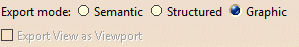
This option offers now the choice between three export modes:
-
Graphic:
This was the only available mode up to Release 11.
It is quick and reliable. It is useful if you want to export a CATDrawing and print it without modifying it.
It is the default mode. -
Structured:
This mode is introduced in Release 11. The exported file can be modified.
For example, in the case of a dimension exported in Structured mode, all the graphic entities representing
the dimension are exported to an Insert/Block. The more complex Drafting elements are exported the same way
whereas the basic geometric elements (lines, arcs, etc) are exported as isolated elements. -
Semantic:
This mode is introduced in Release 11 and is similar to the Structured mode, with the advantage
that linear dimensions are exported as true dimensions (with a default dimension style).
"Default dimension style" entails that most graphic attributes
(such as color, display format of the dimension value, type of arrow, space...) of the dimensions are lost.
-
Export View as Viewport:
Available when Export mode is set to Semantic.
When selected, this option exports Drafting Views as AutoCad Viewports. Drafting Views properties and structure, including visual clipping, are exported as follows:- All the entities of the Drafting View are exported
to the Space Model of the IGES 2D file, at a 1:1 scale and 0° angle.
A Viewport is created for each View in the Paper Space.
The Viewport is positioned in the Paper Space as the View in the Sheet, with scale and orientation management. - All the entities of the Background View are exported into the Paper Space representing the Sheet.
- Views are positioned along the X-axis of the Space Model, without intersection.
- The disposition of the Views in the Model Space is given for indication, but is subject to change.
- The exported visual clipping supports only geometrical entities, not texts or dimensions.
- Visual clippings found in Drafting Views with an angle are not exported.
- The position of geometries in the Model Space is not guaranteed.
- Blocks of details sheet are exploded in the Paper Space sheet.
- All the entities of the Drafting View are exported
to the Space Model of the IGES 2D file, at a 1:1 scale and 0° angle.