 |
This task explains how to
customize the settings for the usage of the 3D XML format, a universal
lightweight XML-based format for quick and easy sharing of 3D data,
enabling rich PLM information to be easily incorporated into technical
documentation, maintenance manuals, marketing brochures, websites, email
communications and many other everyday uses.
|
|
 |
For additional information
concerning the 3D XML format, see the following tasks in the
Infrastructure Guide:
|
|
|
 |
|
|
The 3D XML settings page (Tools > Options > General >
Compatibility > 3D XML) concerns the following settings
categories:
Geometry Representation

XML Tessellation
Provides the representation of a part through a list of organized triangles
(mesh) in XML format.
Can be used for easy geometry exchange.
Static Tessellation
Compressed triangular mesh with static accuracy.
If the assembly is in design mode, the accuracy used is the one specified
in the visualization settings.
If the assembly is in visualization mode, the accuracy of each component
will be that of the associated CGR in the V5 Cache.
Dynamic Tessellation
Compressed representation containing a rough triangular mesh that can be
refined when zooming in to discover details of the geometry (Dynamic Level of Details).
The maximum reachable accuracy is provided by the user at generation time
using the Accuracy setting.
To benefit from Dynamic Level of details, use 3D XML Player or 3DLive
(Explore and Examine window).
When opening a 3D XML file with dynamic tessellation in CATIA V5, the
dynamic tessellation is converted at open time to a static triangular representation (with the accuracy
selected at generation) for compatibility reason.
Export of Lineic Elements
Lineic elements (wires, axis systems, points) are not exported by
default in dynamic and Static Tessellation mode.
To export these elements, you must check the option Tools > Options
> Infrastructure > Product Structure > Cgr Management, Save lineic
elements in cgr.
Lineic elements are never exported in XML Tessellation mode.
|
|
 |
Note the following restrictions related to input documents:
Dynamic Tessellation
- Available only if the Product is in design mode and references only
CATParts. If the user tries to save an assembly
which does not fulfill these conditions, a warning message will be
displayed and the Product will be saved in static tessellation.
XML Tessellation and Static Tessellation
- The user cannot specify the accuracy of the resulting 3D XML.
- If the assembly is in design mode, the accuracy used is the one specified
in the visualization settings.
- If the assembly is in visualization mode, the accuracy of each
component will be that of the associated CGR in the V5 Cache.
|
|
|
|
 |
|
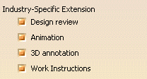
Industry-Specific Extension

To define the different industry-specific extensions corresponding to
the applicative data you want to export, activate the corresponding radio
buttons. Note: Only the extensions for which you have a license will be
displayed.
 By default, all industry-specific extensions are activated.
|
|
|
|
 |
|
Process Document

To define the Process Document object types to be exported, activate
the corresponding radio button.
 By default, this option is valuated to Export both ProductList
and ResourceList.
|
|
|
|
 |
|
Shell Migration Mode
|
|
|
 |
|
|
|
|
|
 |
|
|
|
|
|
|
|
|
|