 |
| This page deals with the options concerning:
|
Translator properties
|
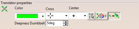 |
| Defines the control points manipulator appearance. |
Color
|
| Defines the color of the control points manipulator. |
 By default, the color is green as shown in the screen capture.
 |
Cross
|
Defines the cross representation for the control points
manipulator.
Four representations are available:
- By lines
- By arrows
- By triangles
- No representation
|
|
By default, the direction are represented by lines. |
Center
|
Defines the center representation for the control points
manipulator.
Three representations are available:
- By a plus
- By a point
- By a circle
|
|
By default, the center representation is a point. |
Pre-selection feedback
|
 Defines whether the
pre-selected element, mesh or point, while editing control point is marked
by a circle. Defines whether the
pre-selected element, mesh or point, while editing control point is marked
by a circle. |
|
By default, this option is not selected. |
 |
Discrete manipulation
|
 Defines whether the
control points manipulator jumps from the control point position to the
cursor position. Defines whether the
control points manipulator jumps from the control point position to the
cursor position. |
|
By default, this option is not selected. |
|
|
Inflate Directions 3D Feedback
|
 Performs the
inflate operation in the work area. Performs the
inflate operation in the work area. |
|
By default, this option is selected. |
Deepness Dumbbell
|
Shows different translator feedback:

The point means that the control point/mesh is moving towards the user.
The x means that it is moving away from the user.
This mode is activated if the angle between the view direction and the
control point modification direction is less than the tolerance set.
|
Advanced
Customization
|
 All Mesh: This is the default
setting for the control point command. When checked, all the control
points are selected by default when geometry is selected. When
unchecked, all the control points are de-selected.
All Mesh: This is the default
setting for the control point command. When checked, all the control
points are selected by default when geometry is selected. When
unchecked, all the control points are de-selected. |
 |
Surface
|
| Defines the control points mesh options while editing a surface. |
Color U
|
| Defines the color along U of the control points mesh. |
|
By default, the color is green as shown in the screen capture. |
Type U
|
| Defines the line type along U for the control points mesh. |
|
By default, the type representation is a solid line. |
Thickness U
|
| Defines the line thickness along U for the control points
mesh. |
|
By default, the line thickness number is 1. |
Color V
|
| Defines the color along V of the control points mesh. |
|
By default, the color is green as shown in the screen capture. |
Type V
|
| Defines the line type along V for the control points mesh. |
|
By default, the type representation is a solid line. |
Thickness V
|
| Defines the line thickness along V for the control points
mesh. |
|
By default, the line thickness value is 1. |
Face
|
| Defines the control points mesh options while editing a face. |
Color U
|
| Defines the color along U of the control points mesh. |
|
By default, the color is red as shown in the screen capture. |
Type U
|
| Defines the line type along U for the control points mesh. |
|
By default, the type representation is a dashed line. |
Thickness U
|
| Defines the line thickness along U for the control points
mesh. |
|
By default, the line thickness number is 1. |
Color V
|
| Defines the color along V of the control points mesh. |
|
By default, the color is red as shown in the screen capture. |
Type V
|
| Defines the line type along V for the control points mesh. |
|
By default, the type representation is a dashed line. |
Thickness V
|
| Defines the line thickness along V for the control points
mesh. |
|
By default, the line thickness value is 1. |
Point
|
| Defines the control points mesh options while editing a point. |
Color
|
| Defines the color of the control points mesh. |
|
By default, the color is green as shown in the screen capture. |
Symbol
|
| Defines the symbol type for the point. |
|
By default, the symbol type is a x-cross. |
|
|
Mouse
|
 |
| Defines the cursor appearance while editing control points. |
|
By default, the cross cursor is selected. |
Furtive Display Variants
|
 |
Control Points
|
|
Defines the color, line type and symbol type of the control points while in
the Furtive Display command. |
|
By default, the color is blue, the line type is bold and the symbol type is
small full square. |
Segmentation
|
|
Defines the color, line type and symbol type of the segments while in the
Furtive Display command. |
|
By default, the color is green, the line type is dashed and the symbol type
is plus. |
Iso-curves
|
|
Defines the color, line type and number of iso-curves along U and V
direction while in the Furtive Display
command. |
|
By default, the color is violet, the line type is dashed and the number of
iso-curves along U and V direction is 1. |
Display the free borders
|
|
Displays the free borders in case of curves and surfaces while in the
Furtive Display command. |
Dress-up
Variants
|
 |
Curve Variant Default
|
Control Points
|
|
Defines the color, line type and symbol type of the control points. |
|
By default, the color is dark green, the line type is dotted and the symbol
type is plus. |
Segmentation
|
|
Defines the color and symbol type of the segments. |
|
By default, the color is green and the symbol type is circle. |
Display the free borders
|
|
Displays the free borders of the curves. |
Surface Variant Default
|
Control Points
|
|
Defines the color, line type and symbol type of the control points. |
|
By default, the color is blue, the line type is dotted and the symbol type
is plus. |
Display control points on edges
|
|
Displays the control points on the edges of the surface. |
Segmentation
|
|
Defines the color and symbol type of the segments. |
|
By default, the color is green and the line type is dashed. |
Iso-curves
|
|
Defines the color, line type and number of iso-curves along U and V
direction. |
|
By default, the color is violet, the line type is dashed and the number of
iso-curves along U and V direction is 1. |
Display the free borders
|
|
Displays the free borders of the surface. |
Face Variant Default
|
Control Points
|
|
Defines the color, line type and symbol type of the control points. |
|
By default, the color is blue, the line type is dotted and the symbol type
is plus. |
Segmentation
|
|
Defines the color and symbol type of the segments. |
|
By default, the color is green and the line type is dashed. |
Iso-curves
|
|
Defines the color, line type and number of iso-curves along U and V
direction. |
|
By default, the color is violet, the line type is dashed and the number of
iso-curves along U and V direction is 1. |
Display the free borders
|
|
Displays the free borders of the face. |
3D Tags
Select the check box to display the 3D tags with a transparent
background and the tagged text with the background color.
By default, this option is cleared.
|