 |
| This page deals with the options concerning:
|
Non-Semantic
|
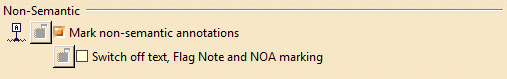 |
| Defines the non-semantic options: |
Mark non-semantic annotations
|
| Defines whether non-semantic annotations (datum elements, datum
targets, geometrical tolerances, linear and angular dimensions) are
marked with a wavy red line in the specification tree and in the
geometry. |
 By default, this option is not selected.
 |
|
|
Switch off text, Flag Note, NOA marking
|
|
Defines whether text, flag note, and NOA marking are considered as
semantic. When selected, the text, flag note, and NOA marking are not
marked with a wavy red line. You can select Switch off text, Flag
Note, NOA marking when Mark non-semantic annotations is
selected. |
|
By default, this option is not selected. |
 |
Grid
|
 |
| Defines the grid options: |
Display
|
| Defines whether the grid is displayed. |
|
By default, this option is not selected. |
Snap to point
|
| Defines whether annotations are snapped to the grid point.
|
|
By default, this option is not selected. |
Allow Distortions
|
| Defines whether grid spacing and graduations are the same
horizontally and vertically. |
|
By default, this option is not selected. |
H Primary spacing
|
| Defines the grid horizontal spacing. |
|
By default, the value is 100mm. |
H Graduations
|
| Defines the grid horizontal graduations. |
|
By default, the number of graduation is 10. |
V Primary spacing
|
| Defines the grid vertical spacing, available only if
Allow Distortions is selected. |
|
By default, the value is 100mm. |
V Graduations
|
| Defines the grid vertical graduations, available
only if Allow Distortions is selected. |
|
By default, the number of graduation is 10. |
|
|
Annotations in Specification Tree
|
 |
| Defines the annotations in specification tree options: |
Under Geometric Feature nodes
|
| Defines that 3D annotations should be displayed under the
geometric feature nodes in the specification tree. This lets you view 3D
annotations under the Part Design or Generative Shape Design feature nodes
to which they are applied. |
|
By default, this option is not selected. |
Under View/Annotation Plane nodes
|
| Defines that 3D annotations should be displayed under the
view/annotation plane nodes in the specification tree. This lets you view
3D annotations under the view node to which they are linked. |
|
By default, this option is not selected. |
Under Annotations Set node
|
| Defines that 3D annotations should be displayed under the
annotation set node in the specification tree, available only if
Under View/Annotation Plane
nodes is selected. |
|
By default, this option is selected. |
|
|
|
|
 |
| Select this option to display True dimensions and 3D
annotations using different colors according to their types and status (true
dimensions, invalid annotations, etc.). |
|
By default, this option is selected. |
| Additionally click Types and colors... to
customize the colors that will be used. The Types and colors
dialog box lets you assign the desired colors to the selected types (true
dimensions, dimensions and annotations on deleted geometry, dimensions and
annotations on unloaded geometry, invalid dimensions and annotations). You
will then be able to visualize the different types using their assigned
colors. |
 |
|
By default, all options are selected and default colors are assigned. |
|
|
|
|
 |
|
Defines whether the annotations are automatically mirrored when
displaying a capture. The annotations are displayed in an easier
readable way. |
|
By default, this option is selected. |