- The Grid
- The Sketch Plane
- The Geometry
- The Constraint
- The Colors
- The Update
Grid
Display
Defines whether the grid is displayed.
![]() By default, this option is selected.
By default, this option is selected.
Adaptive Grid
If selected, this option enables change of grid size as you zoom in or zoom out, in the sketch plane. The current grid size is displayed at the top of the work area.
![]() By default, this option is cleared.
By default, this option is cleared.
Snap to point
Defines whether annotations are snapped to the grid point.
![]() By default, this option is selected.
By default, this option is selected.
Allow Distortions
Defines whether grid spacing and graduations are the same horizontally and vertically.
![]() By default, this option is not selected.
By default, this option is not selected.
H Primary spacing
Defines the grid horizontal spacing.
![]() By default, the value is 100mm.
By default, the value is 100mm.
H Graduations
Defines the grid horizontal graduations.
![]() By default, the number of graduation is 10.
By default, the number of graduation is 10.
V Primary spacing
Defines the grid vertical spacing, available only if Allow Distortions is selected.
![]() By default, the value is 100mm.
By default, the value is 100mm.
V Graduations
Defines the grid vertical graduations, available only if Allow Distortions is selected.
![]() By default, the number of graduation is 10.
By default, the number of graduation is 10.
Sketch Plane
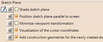
Shade sketch plane
Defines whether a shaded plane is displayed in the Sketcher workbench representing the sketch plane.
![]() By default, this option is not selected.
By default, this option is not selected.
Position sketch plane parallel to screen
Defines if the sketch plane is positioned parallel to the screen when you enter in the Sketcher workbench, otherwise the default orientation is kept. Selecting this option enables Minimize viewpoint transformation check box.
![]() By default, this option is selected.
By default, this option is selected.
Minimize viewpoint transformation
Defines whether to keep the orientation of the sketch axis as close as
possible to original 3D position and orientation.
If you select this option when entering the Sketcher workbench, the
sketch plane aligns itself in such a way that the 2D viewpoint in
Sketcher becomes similar to that of the 3D viewpoint.
3D Viewpoint |
Minimize viewpoint transformation option not selected |
Minimize viewpoint transformation option selected |
![]() By default, this option is not selected.
By default, this option is not selected.
Visualization of the cursor coordinates
Defines whether the cursor coordinates are displayed, near the cursor, within the geometry.
![]() By default, this option is selected.
By default, this option is selected.
Add construction geometries for the newly created sketch
Defines whether the construction elements created in a new sketch should be visible outside Sketcher or not.
![]() By default, this check box is cleared.
By default, this check box is cleared.
Geometry
Create circle and ellipse centers
Defines when you create a circle or an ellipse whether its center is created.
![]() By default, this option is selected.
By default, this option is selected.
Allow direct manipulation
Defines whether you are able to move geometry using the mouse according to the Solving Mode options.
![]() By default, this option is selected.
By default, this option is selected.
Solving Mode...
Click this button to display the solving mode options.
Solving mode for moving elements
- Standard mode: specifies that you can move as many elements as possible with respect of existing constraints.
- Minimum move: specifies that you can move as few elements as possible with respect of existing constraints.
- Relaxation: specifies that you can move elements by re-distributing them over the sketch, globally speaking. This method solves element moving by minimizing energy cost.
![]() By default, the Minimum Move option is selected.
By default, the Minimum Move option is selected.
Drag elements end points included
Defines whether you move geometrical elements with their end points.
![]() By default, this option is selected.
By default, this option is selected.
Constraint

Creates the geometrical constraints
Defines whether the geometrical constraints detected by the SmartPick
tool are created. This option is also available in the Sketcher Tools
toolbar through the Geometrical Constraints capability
![]() .
.
![]() By default, this option is selected.
By default, this option is selected.
Creates the dimensional constraints
Defines whether the dimensional constraints detected by the SmartPick
tool are created. For more information, see
SmartPick. This option is also available in the Sketcher Tools
toolbar thru the Dimensional Constraints capability
![]() .
.
![]() By default, this option is selected.
By default, this option is selected.
Defines whether the geometrical constraints on background elements are detected by the Smartpick tool.
![]() By default, this option is not selected.
By default, this option is not selected.
Automatic Dimensional Constraints Creation
Creates detected internal dimensional constraints automatically as you create a sketch.
![]() By default, this option is cleared.
By default, this option is cleared.
SmartPick...
Click this button to display the SmartPick options. The SmartPick detects multiple directions and positions, and more and more relationships with existing elements. This may lead to confusion due to the rapid highlighting of several different detection possibilities as you point the cursor at different elements in rapid succession.
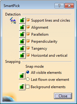
Support lines and circlesDefines whether the line and arc of circle support are detected. AlignmentDefines whether alignment constraint is detected. ParallelismDefines whether parallelism constraint is detected. PerpendicularityDefines whether perpendicularity constraint is detected. TangencyDefines whether tangency constraint is detected. Horizontal and verticalDefines whether horizontal and vertical constraints are detected.
|
Snapping
Snap modeDefines whether the snapping is done on all the visible elements or only on the last flown over element. You can select one of the following options:
Background elementsDefines whether the snapping is possible on the background elements. For more information, see Sketcher User's Guide: Using Smartpick.
|
Colors
Default color of the elements
Defines the color of the geometrical elements.
![]() By default, the color is white. See the screen capture.
By default, the color is white. See the screen capture.
Visualization of diagnosis
Defines whether the diagnosis colors are applied. See Colors diagnoses.
![]() By default, this option is selected.
By default, this option is selected.
Colors...
Click this button to display diagnosis colors options.
Over-constrained elements
Defines the color of over-constrained elements.
![]() By default, the color is magenta. See the screen capture.
By default, the color is magenta. See the screen capture.
Inconsistent elements
Defines the color of inconsistent elements.
![]() By default, the color is red. See the screen capture.
By default, the color is red. See the screen capture.
Not-changed elements
Defines the color of unchanged elements.
![]() By default, the color is brown. See the screen capture.
By default, the color is brown. See the screen capture.
Iso-constrained elements
Defines the color of iso-constrained elements.
![]() By default, the color is green. See the screen capture.
By default, the color is green. See the screen capture.
|
|
Masks of these colors also appear on the sketch features in
the tree to indicate the constraint diagnosis of the respective
sketches. These masks are not displayed for under-constrained sketches (including empty sketches) and Paste Special – Link as results. |
Other color of the elements
Defines the color of the elements which are different of geometrical and diagnosis elements. See Colors for other elements.
Colors...
Click this button to display colors for other elements options.
Protected elements
Defines the color of the protected elements.
![]() By default, the color is yellow as shown by the screen capture.
By default, the color is yellow as shown by the screen capture.
Construction elements
Defines the color of construction elements.
![]() By default, the color is grey as shown by the screen capture.
By default, the color is grey as shown by the screen capture.
SmartPick
Defines the color of the SmartPick assistant elements and symbols.
![]() By default, the color is blue as shown by the screen capture.
By default, the color is blue as shown by the screen capture.
Update
![]() By default, this option is not selected.
By default, this option is not selected.