This page deals with the following categories of options in the Annotation and Dress-Up tab:
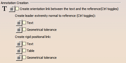
Annotation Creation

These options are taken into account only when creating annotations, not when adding a reference line, for example.
|
|
If Create orientation link between the text and the reference option is cleared, and Snap by default option is selected, orientation links will not be created. |
Create orientation link between the text and the reference
Select this option if you want to create annotation texts along a reference direction. For example, if you select a line when creating a text, the text will be oriented parallel to the line.
By default, this check box is not selected.
This option is applicable only to text without leaders.
Create leader extremity normal to reference
Text
Select this option if you want to create the extremity of text leaders normal to a reference direction. For example, if you select a line when creating a text with leader, the leader will be normal to the line.
By default, this check box is not selected.
Geometrical tolerance
Select this option if you want to create the extremity of geometrical tolerance leaders normal to a reference direction. For example, if you select a line when creating a geometrical tolerance, the leader will be normal to the line.
By default, this check box is not selected.
Create rigid positional link
Text
Select this option to create rigid positional link for text annotations whenever new positional links are created.
By default, this check box is not selected.
Table
Select this option to create rigid positional link for table annotations (between table and reference element) whenever new positional links are created.
By default, this check box is not selected.
Geometrical tolerance
Select this option to create rigid positional link for geometrical tolerance annotations whenever new positional links are created.
By default, this check box is not selected.
Allow attachment points selection during positional link creation
Select this check box to choose the attachment points of an annotation during creation of a positional link.
By default, this check box is selected.
Move

|
|
If Snap by default option is selected and Create text along reference option is cleared, orientation links will not be created. |
Configure snapping
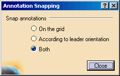
Click the Configure snapping button to define how snapping should be performed. In the dialog box that appears, specify whether you want annotations to be snapped on the grid, according to the leader orientation, or both. This will apply to the annotations selected in the Annotation Creation area.
By default, Both is selected.
Snap by default (SHIFT toggles)
Select this option to activate snapping by default when creating or handling annotations. Pressing the Shift key will enable you to temporarily deactivate snapping. Note that snapping is performed according to the options set in the Snapping Annotations dialog box.
With this option unselected, snapping is not active. In this case, pressing the Shift key will enable you to temporarily activate it.
By default, this option is selected.
- From V5 R15 onwards, the Snap to Point option on the General tab no longer applies to annotations. Only this option is taken into account.
Before V5 R15, this option used to be called Activate Snapping (SHIFT toggles). It has been renamed for clarity reasons.
2D Component Creation

Apply scale at creation to compensate view scale
Select this option if you want all 2D component instances to have the same size when you create them, no matter what the view scale is.
This lets you create 2D component instances whose size is independent from the view scale so that they always look the same. You can use them as symbols, for example.
When you instantiate a 2D component in a view, the reciprocal of the view scale is applied to the 2D component.
If you want to use as symbols 2D components with text, activate both the Apply scale at creation to compensate view scale setting and the Apply Scale property for the text (in Edit > Properties): the size of both the 2D component and its text will then be independent from the view scale.
By default, this option is not selected.
Prevent direct manipulation
Select this option to make it impossible to move 2D components using the mouse.
By default, this option is not selected.
Prevent direct scaling
Select this option to make it impossible to scale 2D components using the mouse.
By default, this option is not selected.
Balloon Creation
3D associativity
Select this option to indicate that you want to associate balloons with information from the 3D.
By default, this option is selected.
Additionally, select from the list the kind of balloons you want to create or generate: the numbering of parts within an assembly (default option), the instance name or the part number.
By default, Numbering is selected.
Table

Recompute table when editing cell
Select this option if you want a table to be resized while you are editing a cell. If it is not selected, the table is resized after closing the Text Editor.
By default, this option is selected.
Do not split table on several sheets
This option is available only when certain licenses are installed.
With certain licenses, when creating a table, a Bill of Material or when importing a CSV file, tables can be split automatically on several sheets, according to their size and location. Select this option if you want to keep tables on a single sheet.
By default, this option is not selected.
Area Fill

Ask for deletion of geometry support
When this option is selected, a message appears each time you delete an area fill, to ask you if you want or not delete the area fill support geometry.
When this option is not selected, the message does not appear and the area fill support geometry is not deleted.
When deleting isolated area fills, this message does not appear, as there is no support geometry to delete.
By default, this option is selected.
Area Fill detection optimized for geometry
Define the tolerance mode allowed when creating an area fill profile.
- Generated or sketched: Select this option when creating area fills mainly on generated or sketched geometries.
By default, this option is selected.
- Imported from external format: Select this option when creating area fills mainly on views imported from external formats.
