This page deal with options concerning:
Report
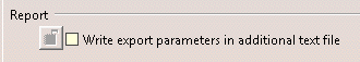
When selected, generates a text file with _param.txt suffix when you export laser projection data. It contains the settings and parameters.
Default File Path
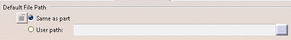
Defines the default storage path for the exported file, either the same as the current part, or one you enter.
Export File Structure
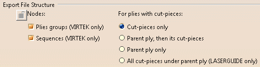
Specifies the structure of the export file. Select the desired option:
- Nodes
- Defines the elements to export as layers.
![]() By default, Plies groups and Sequences are selected.
By default, Plies groups and Sequences are selected.
- For Plies with cut-pieces
-
Defines the organization of plies and cut-pieces in the export file:
- Cut-pieces only: Only cut-pieces are exported, each under its own node.
- Parent ply, then its cut-pieces: Exports the ply and its cut-pieces in distinct nodes, at the same level, the ply node being followed by the cut-pieces nodes.
- Parent ply only: Only the parent ply is exported, in its own node.
- All cut-pieces under parent ply (LASERGUIDE only): Creates an additional level for each ply (this layer is called a SEQUENCE command in the LASERGUIDE file). The ply (if no cut-piece), or the cut-pieces are exported under this level, enabling the projection of all the cut-pieces of a given ply together.
Export
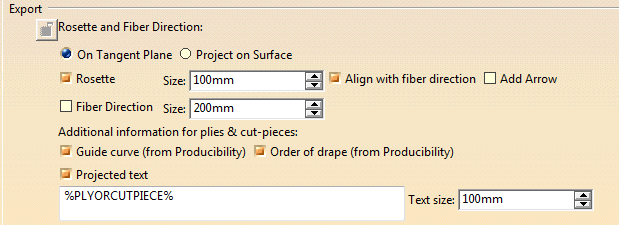
Rosette and Fiber Direction
- Rosette
- Select this check box to export the rosette.
- Define the Rosette size: Size of the rosette transferred at each seed point or ply center.
- Select On Tangent Plane, to place the rosette on a
plane tangent to the ply, at the seed point,
or Project on Surface, to place the 0° and 90° curves of the rosette on the ply geometry.
When projected on a surface, very large rosette curves are created up to the limits of the surface. - For both options:
- The 0° curve is longer than the 90° curve.
- Both curves are exported as guide curves.
- Select Add Arrow, if required.
![]() By default, Rosette size is set to 100 mm, On Tangent Plane is selected,
Add Arow is not selected.
By default, Rosette size is set to 100 mm, On Tangent Plane is selected,
Add Arow is not selected.
- Fiber Direction
- Select this check box
to export the fiber direction for plies and cut-pieces.
The fiber direction is represented by a curve, starting at the point where the rosette is displayed.- Enter the size of the fiber direction
curve.
For a better visibility, it must be larger than the Rosette Size, and still lie completely inside the ply geometry.
When projected on a surface, a large fiber direction curve is created up to the limits of the surface. - Select On Tangent Plane, to place the fiber direction curve on a plane tangent to the ply, or Project on Surface to place the fiber direction on the ply geometry.
- Enter the size of the fiber direction
curve.
![]() By default, Fiber Direction Size is set to 200 mm, On Tangent Plane
is selected.
By default, Fiber Direction Size is set to 200 mm, On Tangent Plane
is selected.
- Additional information for plies & cut-pieces
- Specifies additional information to export. Select the required
options.
- Guide curve (from Producibility): The producibility curve input is exported as a polyline guide curve.
- Order of drape (from Producibility): The producibility contours inputs are exported as polylines.
- Projected text:
Provides an easy way to export a text to project on the mold. This
option can be combined with Stacking Text.
- In VIRTEK format, the text is added to the file as a Text Identifier ("T"Key)
- In LPT format, the text is added with a <TEXT> node.
- In LASERGUIDE and LAP formats, the text is added with a
<TEXT> command.
- The 3D text is placed at
the ply/cut-piece seed or central point in the transferred rosette plane
and direction.
It can contain key words:
%PARTFILENAME%
%PARTNUMBER%
%PLYGROUP%
%SEQUENCE%
%PLY%
%CUTPIECE%
%PLYORCUTPIECE%
%MATERIALID%
%MATERIALNAME%
%DIRECTIONNAME%
%DIRECTIONVALUE%
- Text size
- Defines the size of the
text to project.
Note that it is ignored by the LASERGUIDE format.
![]() By default, it is set to 100 mm.
By default, it is set to 100 mm.
Preview
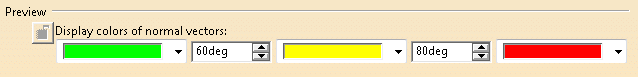
Specifies the colors and warning/limit angles between the normal vector and
the beam
(The beam is the line between the projector and the
discretization point).
Predefined Laser Projectors
![]()
Specifies where the description file of laser projector types is stored.
This description is used to populate the Projector type list
in Laser Projector.
Below is an example of a description file:
PROJECTOR_TYPE MIN_DIST MAX_DIST MAX_H_ANGLE MAX_V_ANGLE LENGTH WIDTH DEPTH COLOR_R COLOR_G COLOR_B
Laser A 1500mm 5000mm 40deg 40deg 400mm 200mm 150mm 100 100 100
Laser B 2000mm 6000mm 45deg 40deg 500mm 250mm 200mm 255 255 0
Laser C 2500mm 7000mm 50deg 50deg 600mm 300mm 250mm