|
-
Click Twin Joggle
 in the
Aerospace Sheet Metal toolbar. in the
Aerospace Sheet Metal toolbar.
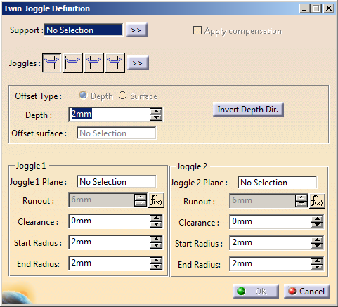
The Twin Joggle Definition
dialog box appears.
-
In the Support
box, select the surfacic flange or the web.
-
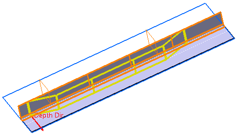
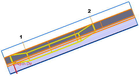
Select the planes for both joggles.
The twin joggle is previewed:
|
-
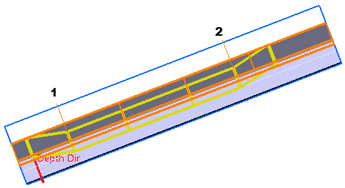
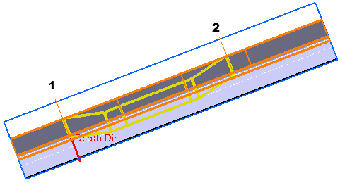
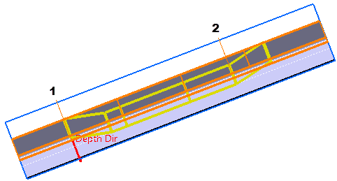
Define the twin joggle type:
1 corresponds to Joggle 1
and 2 to Joggle 2.
- Outside Planes
 : :
- Inside Planes
 : :
- Outside / Inside Planes
 : :
- Inside / Outside Planes
 : :
|
-
Optional: To
define a compensation, select the Apply
compensation check box.
For more information, see Creating a Joggle.
-
Define the offset type and parameters:
- Depth:
- Enter the gap value between the support
surface and the joggle offset surface.
- Reverse the depth direction either by
clicking Invert Depth Dir in the dialog box or
the red arrow in the 3D area.
|
- Offset Surface:
Select an offset surface.
For more information, see Creating
a Joggle by Selecting
an Offset Surface.
|
-
For each joggle, define the following parameters:
- Runout:
Length of the joggle area.
- Clearance:
Gap between the joggle plane and the end of the joggle area.
- Start Radius:
Radius value at the start of the joggle area.
- End Radius:
Radius value at the end of the joggle area.
|
 |
- If you modify the depth, the runout adjusts
automatically by using the formula applied to the runout
parameters. To manually modify it, right-click the
Runout box, and select
Formula > Deactivate.
- If the support is a closed surface, the
Invert Twin Joggle Dir.
button and an arrow appear in the dialog box and in the 3D
area to reverse the direction of the twin joggle.
|
-
Click OK.
The twin joggle (identified as Twin Joggle.xxx) is created.
|
|
Two twin joggles cannot intersect, and a single joggle
cannot be created inside a twin joggle. |
|