|
 |
This section
explains the calculations related to folding/unfolding operations. |
 |
-
Click SheetMetal Parameters
 . .
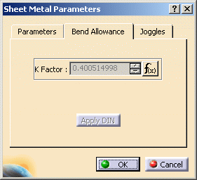
| The Sheet Metal Parameters dialog box is displayed. |
| The second tab concerns the bend
allowance. |
| |
 |
|
| |
Bend Allowance
|
| |
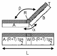
The bend allowance corresponds to the unfolded
bend width of swept walls and stamps. |
|

|

|
|
bend < 90deg |
bend > 90deg |
| |
- L is the total unfolded length
- A and B the dimensioning lengths as
defined on the above figure. They are similar to the DIN definition.
|
 |
Be aware that the example above is a
textbook case describing a planar flange support with a constant angle. |
| |
|
| |
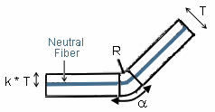
Physically, the neutral fiber represents the
limit between the material compressed area inside the bend and the extended
area outside the bend. Ideally, it is represented by an arc located inside
the thickness and centered on the bend axis. |
|
The K factor defines the neutral fiber position:
- W = a * (R + k * T)
where:
- W is the bend allowance
- R the inner bend radius
- T the sheet metal thickness
- a the inner bend angle in
radians.
If b is the opening bend
angle in degrees:
- a = p *
(180 - b) / 180
|
 |
|
When you define the sheet metal parameters, a literal
feature defines the default K Factor and a formula is applied to implement
the DIN standard. This standard is defined for thin steel
parts. Therefore the K Factor value ranges between 0 and 0.5. |
 |
The DIN definition for the K factor slightly differs.
- W = a * (R + k' * T/2)
- Therefore k' = 2 * k and ranges from 0 to 1.
|
| |
This formula can be deactivated or modified by
right-clicking in the K factor field and choosing an option from the
contextual menu. It can be re-activated by clicking the Apply DIN button.
Moreover, the limit values can also be modified. |
| |
|
| |
When a bend is created, its own K Factor literal is
created.
Two cases may then occur:
- If the Sheet Metal K Factor has an activated formula using the
default bend radius as input parameter, the same formula is activated on
the bend K Factor replacing the default bend radius by the local bend
radius as input.
- In all other cases, a formula "equal to the Sheet Metal K Factor" is
activated on the local bend K Factor.
This formula can also be deactivated or modified.
|
| |
Bend Deduction
|
| |
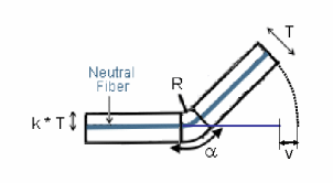
When the bend is unfolded, the sheet metal
deformation is thus represented by the bend deduction V,
defined by the formula:
- L = A + B + V
- (refer to the previous definitions).
Therefore the bend deduction is related to the K factor using the
following formula:
- V = a * (R + k * T) - 2 * (R + T)
* tan ( min(p/2,a)
/ 2)
|
 |
| |
This formula is used by default. However, it is possible to
define bend tables on the sheet metal parameters. These tables define
samples: thickness, bend radius, open angle, and bend deduction. In this
case, the bend deduction is located in the appropriate bend table, matching
thickness, bend radius, and open angle. If no accurate open angle is found,
an interpolation will be performed. |
| |
|
| |
When updating the bend, the bend deduction is
first computed using the previously defined rules. Then the bend allowance
is deduced using the following formula:
W = V + 2 * (R + T) * tan ( min(p/2,a)
/ 2)
|
 |
When the bend deduction is read in the bend
table, the K factor is not used. |
|
 |
![]()
 .
.


![]()